Theory
In contrast to Michelson's original theory and most educational texts we consider the problem from the outset in the reference frame of the interferometer (in which after all the observations are made). In this case, the only aspect of relevance here is the speed of light in a given direction depending on the relative velocity of the moving 'ether' (in which by assumption the speed of light is isotropic). Michelson assumed for his theory that the light is 100% dragged by the ether and has a constant speed c in the ether's reference frame regardless of the relative velocity of the light source. This was in principle an unfounded assumption and in fact would appear to contradict Fizeau's experiment (which was already well known at the time), since a 100% drag would require an infinite refraction index and thus, paradoxically, imply a zero propagation speed of light. The only justification for assuming a 100% drag would be to hypothesize that the luminiferous ether is a special medium that affects light differently to normal matter, and we shall use this assumption here for the sake of the argument).Aberration of Plane Waves
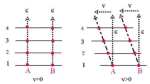
In order to obtain the correct optical paths of the light signal in the interferometer frame, we have to consider how the orientation of the wave front of a plane depends on the velocity of the ether medium. In the left part of the below illustration we have the wave front propagation upwards with speed c for the ether at rest (v=0)(4 positions are indicated). The right part shows the wave front for the ether moving with velocity v to the left. The two points A and B on the wave front move now on an inclined path, but the orientation of the wave front is unchanged. Since the normal to the wave front defines the direction of propagation of the wave, there is thus no aberration occurring here; the wave is still moving vertically upwards with speed c, and there is no change in the phase difference between any two points.
Fig.1 : Wave propagation for resting and moving ether
The speed of light in the interferometer frame is therefore
(1) ci = c+v.cos(v,c)
where cos(v,c) is the component of the ether velocity vector along the direction of light propagation. If the two directions are co-aligned we have thus the usual relationship ci = c±v , whereas for the two directions being orthogonal, we have ci = c (this is what Michelson actually correctly assumed in his original theory, adding only later an aberration effect based on the opinions of Potier and Lorentz).An importance consequence of Eq.(1) (which to the author's knowledge has not been addressed yet in the literature at all), is the fact that the speed and thus the wavelength of light in the interferometer frame is not isotropic, and thus the usual reflection law does not apply anymore. A light beam falling onto a mirror at a 45o angle will in general not be reflected by 90o (as assumed in the literature throughout) but will deviate from this by a certain amount, which in turn changes the optical path lengths. In the next section we will determine this deviation angle as a function of the ether speed and direction, and in the subsequent section we will work out the correct phase difference in the optical paths on this basis. In contrast to the usual theory, we assume the velocity vector to have an arbitrary direction in the optical plane of the instrument.
Reflection Angle
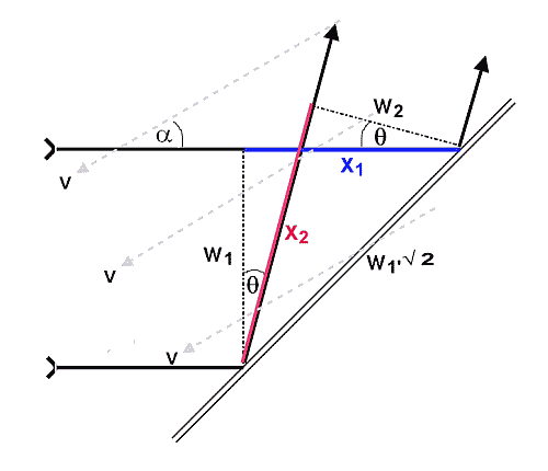
In order to calculate the deviation angle, we have to consider the geometrical relationships as illustrated below (Fig.2). We assume the incident plane wave of width w1 going horizontally from left to right and hitting the mirror at 45o (as shown above, this condition is independent of the ether velocity and can thus be considered as set).
Fig.2: Condition for beam reflection in reference frame of mirror (v=ether velocity)
According to (1), the wavelength of the light before reflection is (with v the velocity of the ether relative to the mirror and α the angle between v and the light beam direction)
(2) λ1 = (c -v.cos(α))/f = λ0.(1 -v/c.cos(α))
and the wavelength after reflection(3) λ2 = (c -v.cos(90-α-θ))/f = λ0.(1 -v/c.sin(α+θ))
where θ is the deviation angle of the reflected beam from the vertical.The number of wavelengths in the length x1 (the path difference between the two sides of the incoming beam) is
(4) n1 = x1/λ1
Correspondingly we have for the reflected beam(5) n2 = x2/λ2
The condition for the interference maximum is then(6) n2 = n1
We van calculate the angle θ from (2)-(6) by using the geometrical relationships evident from the diagram above (noting that the mirror is set at a 45o angle)(7) x1 = w1
(8) x2 = w1.√2.cos(π/4-θ)
This yields(9) (cos(θ)+sin(θ)) / (1 -v/c.sin(α+θ)) = 1/(1 -v/c.cos(α))
which in a first order approximation assuming v<<c and θ<<1 simplifies to(10) θ ≈ v/c.(cos(α)-sin(α))
As expected due to the symmetry of the problem, in case of the ether velocity being parallel to the mirror surface, the deviation angle is zero i.e. the reflection is exactly about a right angle, but in all other cases it is larger or smaller than this by an amount of the order v/c.Phase Difference between Optical Paths
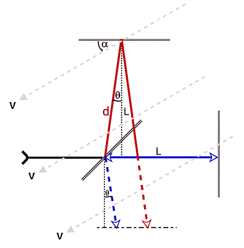
Taking the correct wavelengths in the optical paths and associated reflection angle (as derived in the previous) into account, the number of wavelengths in the longitudinal and 'transverse' optical paths between the semi-transparent 45o mirror and the two reflecting mirrors are (see Fig.3 below)
Fig.3: Beam paths in reference frame of interferometer (v = relative velocity of medium)
(11) Nl = L/λ0/(1 -v/c.cos(α)) + L/λ0/(1 +v/c.cos(α)) =
= 2L/λ0/(1-v2/c2.cos2(α)) ≈
≈ 2L/λ0.(1+v2/c2.cos2(α))
(12) Nt = d/λ0/(1 -v/c.cos(π/2-α-θ)) + d/λ0/(1 +v/c.cos(π/2-α+θ)) =
= L/λ0/cos(θ)/(1 -v/c.sin(α+θ)) + L/λ0/cos(θ)/(1 +v/c.sin(α-θ)) ≈
≈ L/λ0.(1+θ2/2) .(2+v/c.(sin(α+θ)-sin(α-θ)) + v2/c2.(sin2(α+θ)+sin2(α-θ)) ≈
≈ 2L/λ0.(1+v2/c2.(3/2-sin(2α))
(note that the additional paths to the optical plane (dashed red and blue in Fig. 3) are of the same length and have the same wavelength (as they are parallel), so there is no change in the phase difference through this).
In contrast, the corresponding equations for the original theory of Michelson and Morley (that is incorrectly assuming right angle reflection in the interferometer frame and aberration of the normal to the wave front between the interferometer and ether frame (see Sect.'Aberration of Plane Waves' above ) the corresponding equations are
(13) NlMM ≈ 2L/λ0.(1+v2/2c2.(1+cos(2α))
(14) NtMM ≈ 2L/λ0.(1+v2/2c2.(1+sin(2α))
which results from the equations (in contrast to (1))(15) clMM = √ (c2+v2 ∓2cv.(cos(α∓v/c.sin(α))
(16) ctMM = √ (c2+v2 ∓2cv.(sin(α±v/c.cos(α))
If we subtract (12) from (11) we obtain the phase difference between the two beams(17) Nl-Nt ≈ 2L/λ0.v2/c2.(cos2(α)+sin(2α)-3/2)
whereas for the incorrect theory of Michelson and Morley we obtain from (13) and (14)(17) (Nl-Nt)MM ≈ 2L/λ0.v2/2c2.cos(2α)
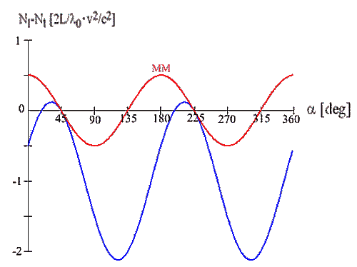
In Fig.4 below, (17) and (18) are graphically displayed as a function of the ether velocity angle α , normalized to 2L/λ0.v2/c2
Fig.4: Variation of phase difference with varying ether velocity direction α ; red: Michelson-Morley theory; blue wave optics approach)
It is obvious that the two curves coincide only in two points, namely when the ether velocity is parallel to the 45o mirror. In this case the phase difference is zero because the reflection is exactly at a right angle as per (10). The theory of Michelson and Morley incorrectly predicts zero phase difference also when the velocity vector is perpendicular to the mirror surface, as it neglects the deviation of the reflection angle from a right angle as per (10). Instead, the other two zero points are obtained from (17) occur at approximately 18.4o and 198.4o. Overall, the amplitude of the phase variation should be more than twice that assumed by Michelson and Morley, with the phase difference staying almost completely negative throughout due to the actual deviation from right-angle reflection for the transverse beam.